HDLbits刷题笔记—Exams/2014 q4b
作者:互联网
Description:
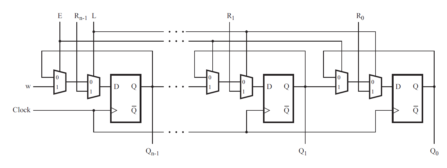
Consider the n-bit shift register circuit shown below:

Write a top-level Verilog module (named top_module) for the shift register, assuming that n = 4. Instantiate four copies of your MUXDFF subcircuit in your top-level module. Assume that you are going to implement the circuit on the DE2 board.
- Connect the R inputs to the SW switches,
- clk to KEY[0],
- E to KEY[1],
- L to KEY[2], and
- w to KEY[3].
- Connect the outputs to the red lights LEDR[3:0].
(Reuse your MUXDFF from exams/2014_q4a.)
module top_module (
    input [3:0] SW,
    input [3:0] KEY,
    output [3:0] LEDR
); //
    MUXDFF s1(KEY[3],KEY[1],SW[3],KEY[2],KEY[0],LEDR[3]);
    MUXDFF s2(LEDR[3],KEY[1],SW[2],KEY[2],KEY[0],LEDR[2]);
    MUXDFF s3(LEDR[2],KEY[1],SW[1],KEY[2],KEY[0],LEDR[1]);
    MUXDFF s4(LEDR[1],KEY[1],SW[0],KEY[2],KEY[0],LEDR[0]);


endmodule

module MUXDFF (
input w,
input e,
input r,
input l,
input clk,
output q);
    always@(posedge clk)begin
        case({e,l})
            2'b00:q<=q;
            2'b01:q<=r;
            2'b10:q<=w;
            2'b11:q<=r;
        endcase
    end


endmodule
标签:LEDR,MUXDFF,HDLbits,SW,module,q4b,Exams,KEY,input 来源: https://www.cnblogs.com/tao1997/p/15520342.html