Switch regulator 和 Linear regulator
作者:互联网
Switch regulator(开关稳压器)和 Linear regulator(线性稳压器)是现在常用的电源器件(DC-DC器件暂且不提),但是两者有很大的区别,线性稳压器是比较 “古老的物种” ,电源转换效率很低,而开关稳压器我也不知道是什么时候发明的,但是电源转换效率很高,使得开关型电源大行其道。两者具体原理和区别我从网上找来资料做一个简单的记录。
switch(开关)方式最主要的好处是效率(Po/Pi)的提升, 而且可以做升压(boost), 降压(buck), 升降压(boost-buck). 而Linear regulator 效率低于switch, 由于输出电压小于输入电压。目前Power supply 需求大功率(etc. 200W) 都是采用switch. 而小电流(mA)的就比较常见用regulator.
线性稳压器原理:
引自百度百科:线性稳压器(Linear Regulator)使用在其线性区域内运行的晶体管或 FET,从应用的输入电压中减去超额的电压,产生经过调节的输出电压。其产品均采用小型封装,具有出色的性能,并且提供热过载保护、安全限流等增值特性,关断模式还能大幅降低功耗。线性稳压器内部原理图如下图(PMOS):

用我很有限的模电知识来解释一下这个原理图:输入电源连接到PMOS的S极,MOS管的D极作为稳压后的电源输出,G极接到一个运放(比较器)的输出端,运放的正极接到一个反馈电阻分压网络,负极接到一个参考电压源,这样构成了一个反馈系统。系统反馈稳定之后的结果就是R1和R2电阻分压得到R2的两端的电压和Vref电压相同,这时候有:
Vout * R2/(R1 + R2) = Vref
Vout = Vref * (R1 + R2) / R2 = Vref *(1 + R1 / R2)
我也不知道我解释的有什么问题,反正模电水平就这样了,要想证明那就实验一下,懒得搭电路了,用proteus软件仿真一下试试结果,proteus的仿真原理图如下:

完全是按照上面的线性稳压器的结构示意图画的仿真电路,实验输入电压是24V,R1=20K,R2=10K,Vref=1.25V,负载电阻1K,根据计算得到Vout = 1.25 * (1 + 20 / 10) = 3.75V,仿真结果是3.74V,基本满足计算结果。实验算是成功了,但是将负载电阻的阻值降低之后输出电压下降的很明显,应该是因为使用的PMOS管或者运放不满足高输出电流的需求。
如果还有一点很要我惊讶的是输出电流为3.98mA,输出电流为3.74mA,也就是输入功率Pi = 3.98 * 24 = 95.52mW,输出功率
Po = 3.74 * 3.74 = 13.9876mW,这个能量转换效率有点太低了。线性稳压器的效率估算公式为:

可以得出一个结论,如果输入电压和输出电压压差很大的话,线性稳压器的工作效率会很低,消耗掉的无用功会以热量的形式从线性稳压器上散出去,导致发热严重。
参考文章:http://tech.hqew.com/fangan_1738680 , http://www.mr-wu.cn/understanding-ldos/
开关稳压器原理:
引自百度百科:开关稳压器使用输出级,重复切换“开”和“关”状态,与能量存贮部件(电容器和感应器)一起产生输出电压。它的调整是通过根据输出电压的反馈样本来调整切换定时来实现的。
引自Wikipedia:A buck converter (step-down converter) is a DC-to-DC power converter which steps down voltage (while stepping up current) from its input (supply) to its output (load). It is a class of switched-mode power supply (SMPS) typically containing at least two semiconductors (a diode and a transistor, although modern buck converters frequently replace the diode with a second transistor used for synchronous rectification) and at least one energy storage element, a capacitor, inductor, or the two in combination. To reduce voltage ripple, filters made of capacitors (sometimes in combination with inductors) are normally added to such a converter's output (load-side filter) and input (supply-side filter).[1]
Switching converters (such as buck converters) provide much greater power efficiency as DC-to-DC converters than linear regulators, which are simpler circuits that lower voltages by dissipating power as heat, but do not step up output current.[2]
Buck converters can be highly efficient (often higher than 90%), making them useful for tasks such as converting a computer's main (bulk) supply voltage (often 12 V) down to lower voltages needed by USB, DRAM and the CPU (1.8 V or less).
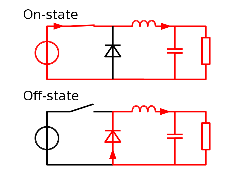
开关稳压器的开关原理如下图:

当开关闭合的时候左边的电源直接供给给右边的负载(电感、电容、电阻),当开关打开的时候,电源无法直接供电给负载,但是右边的储能器件(电感和电容)会将自身存储的电能通过续流二极管形成回路输出到负载电阻上去。如果我们加上一个反馈电路,通过检测输出电压的大小来调整开关的频率和占空比可以实现输出一个固定电压值。这是一个原理上的解释,正真的开关型稳压器芯片内部比这个要复杂很多。
标签:输出,Linear,R2,regulator,开关,Switch,电压,线性,稳压器 来源: https://blog.51cto.com/u_12956289/2917708